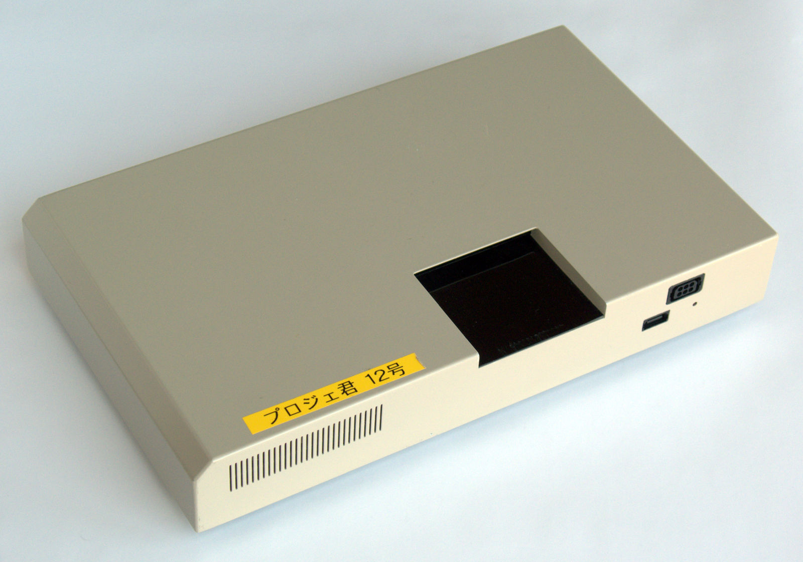
The Video Boy plays Nintendo Virtual Boy games on a TV or monitor. As with many of Nintendo's development tools, it was made by Intelligent Systems. These were used to record video or screenshots; it's said that this particular unit was used by the venerable Nintendo Power.
Contents:
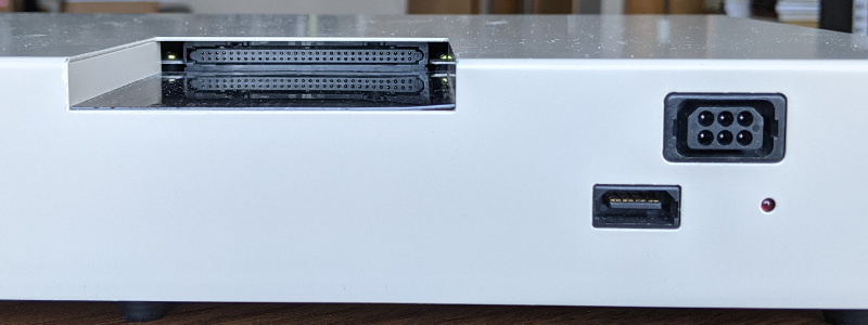
The Virtual Boy inputs are on the top and front of the unit. From left to right: cartridge slot, link cable port, and controller port. There's also a red power LED. A cartridge goes in with the label facing down; it plugs directly into a Virtual Boy main board.
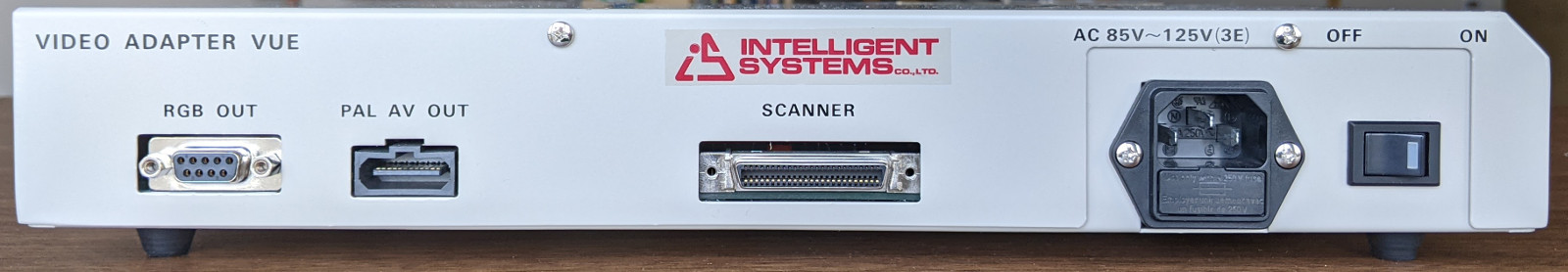
Note that the name shown here is "Video Adapter VUE". "Video Boy" appears nowhere on this device, but it is found in the instructions as "VIDEO-BOY (VUE)" and on the Intelligent Systems site as ビデオボーイ or videoboy.html.
The AV multi-out is PAL, which is 50 FPS like the Virtual Boy; this avoids a more complicated and lossy scan conversion to ~60 FPS NTSC.
The unit came with a DB9 to 3xRCA cable for the RGB OUT; I haven't tested it, lacking a monitor that takes raw RGB. The SCANNER port connects to a development headset; I don't have one.
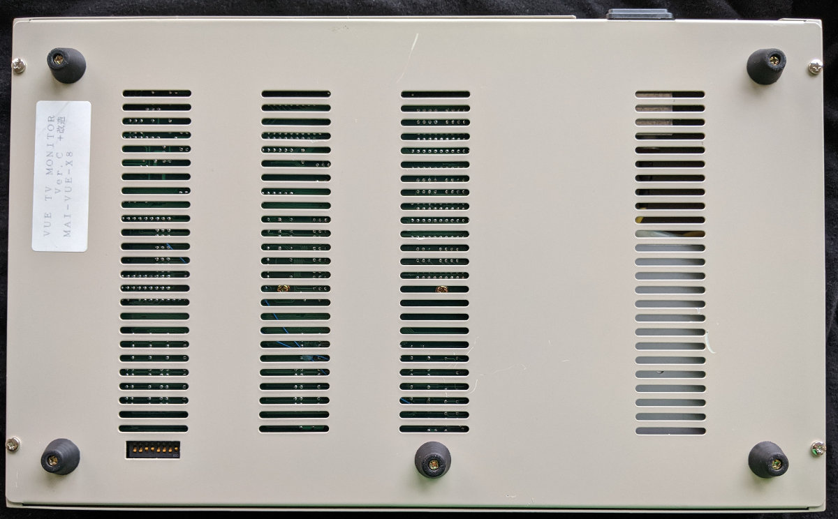
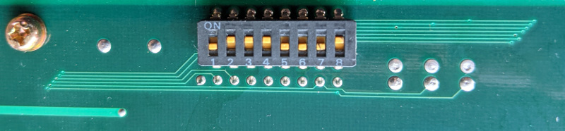
This row of switches, SW1, is exposed on the bottom of the unit. The initial setting was: 1 off, 2 on, 3 on, 4 on, 5 off, 6 off, 7 off, 8 on.
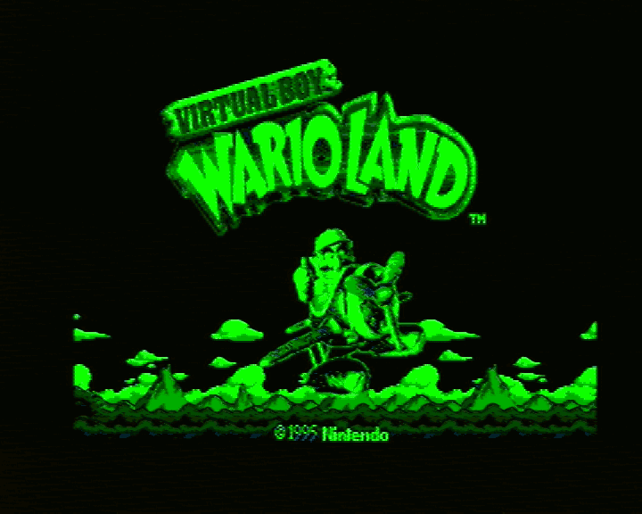
7 and 8 control which display is shown: 8 controls the left, rendered in Virtual Boy red, 7 is the right, rendered in green. With both 7 and 8 on, left and right are combined, this was intended as anaglyph 3D. See the video output below.
Switching 5 on prevents anything from working. I didn't notice any effect from switching the others.
There's an image of the instructions which describes the switches, unfortunately it's low resolution. I think it says "don't use" for 5 and 6, and 1-4 are for setting some integer, "1=MSB, 4=LSB, ON=0, OFF=1".
There are nearby unpopulated jumper pads, and a set of pads marked "CL" which seem to be cut traces. This may have been hardwired when the switch wasn't installed.
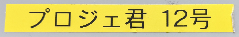
The top label says "プロジェ君 12号", approximately "Project No. 12".
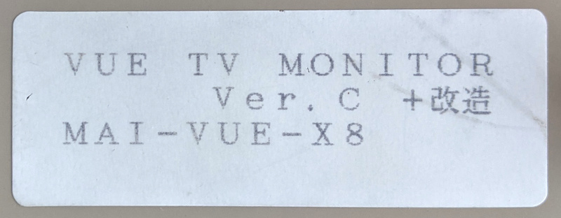
The bottom label says "VUE TV MONITOR", identifying the board inside. "Ver. C" indicates the third or fourth version, and "+改造" is "plus retrofit", perhaps indicating the various jumper wire patches. "MAI-VUE-X8" identifies the internal Virtual Boy main board.
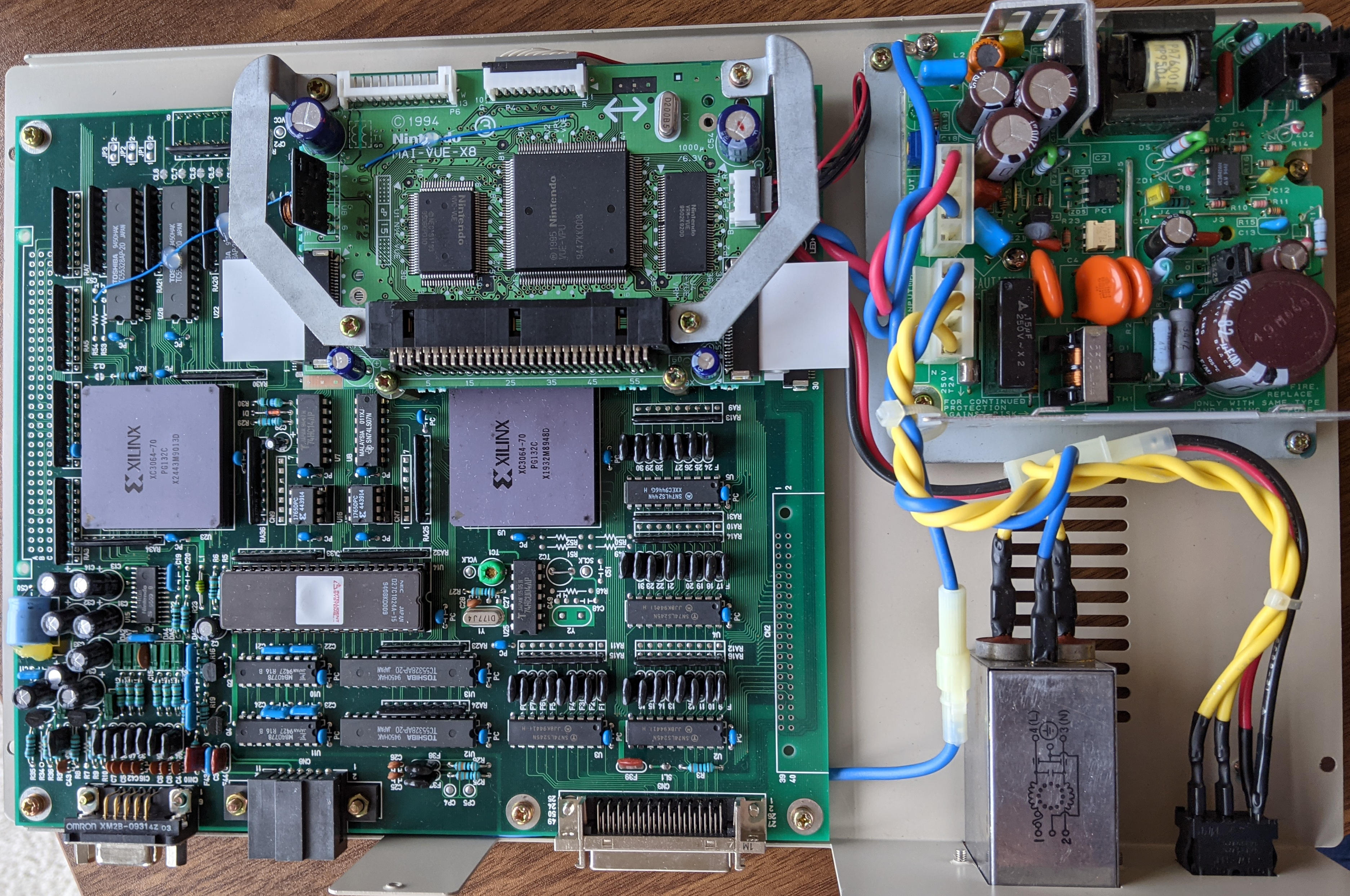
The monitor board (left) has a Virtual Boy main board mounted on top of it (center top between the metal braces). The right side of the case is taken up by the power supply.
The Virtual Boy generates an image by sweeping a column of light horizontally. To convert this to the rows of a PAL TV signal, at least one frame must be buffered and rotated; the monitor board performs this conversion.
Note that the monitor board has unpopulated connector pads on the left (CN1, label not visible) and lower right (CN2). I think this same board can be configured to go into a VUE-DEBUGGER development unit (see PAL monitor), CN1 would be where it plugs into the debugger bus.
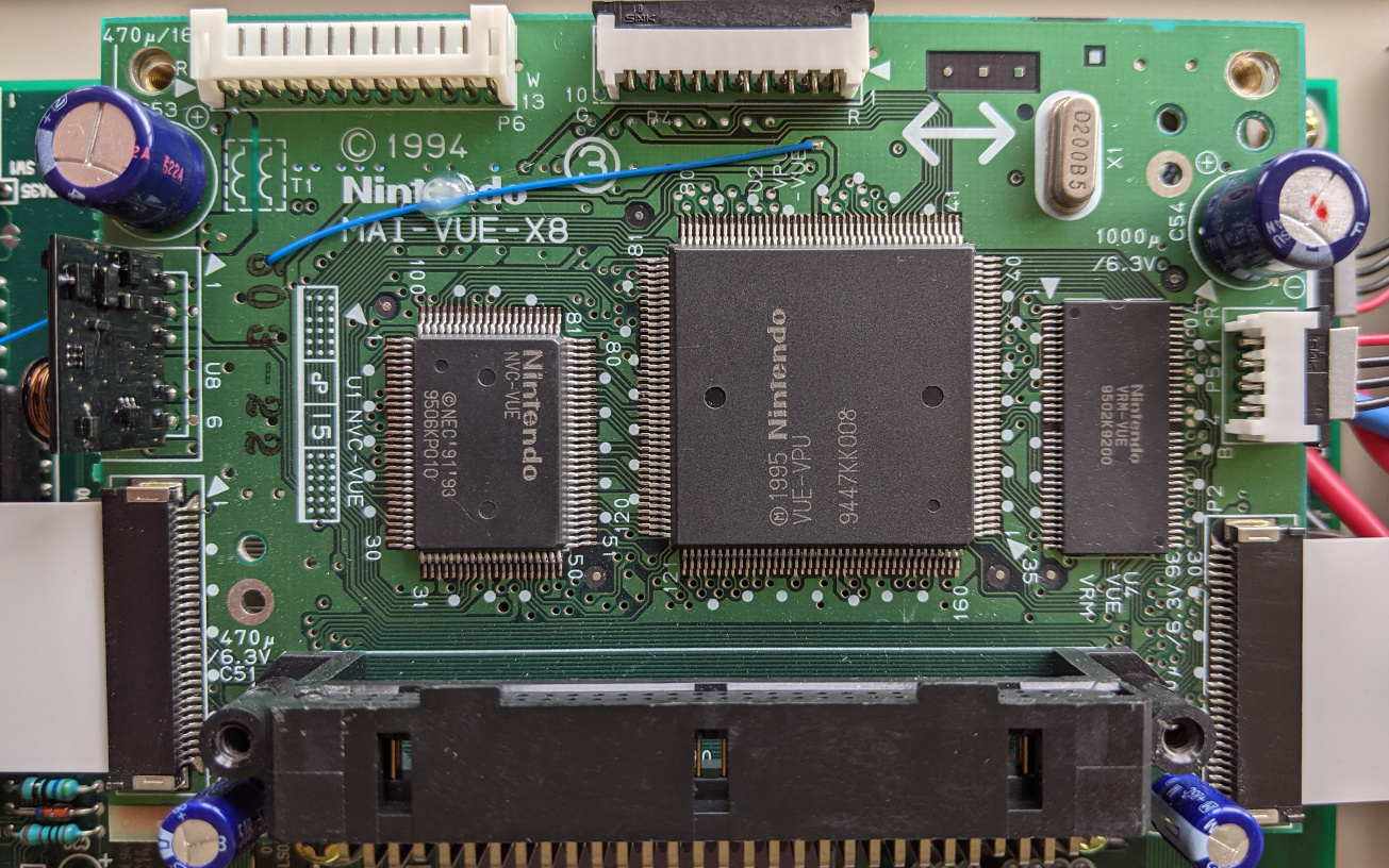

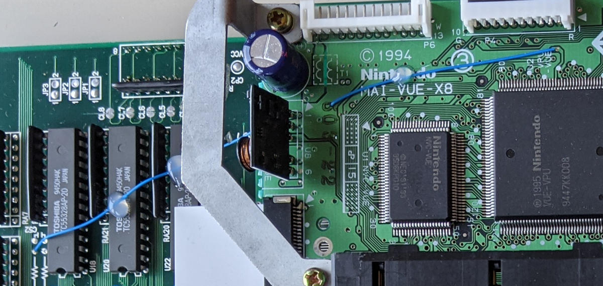
The main board is the heart of a Virtual Boy. This seems to be an early or development board, MAI-VUE-X8, (c) 1994. (A production board is VUE-MAI-01, (c) 1995.)
For info on Virtual Boy hardware:
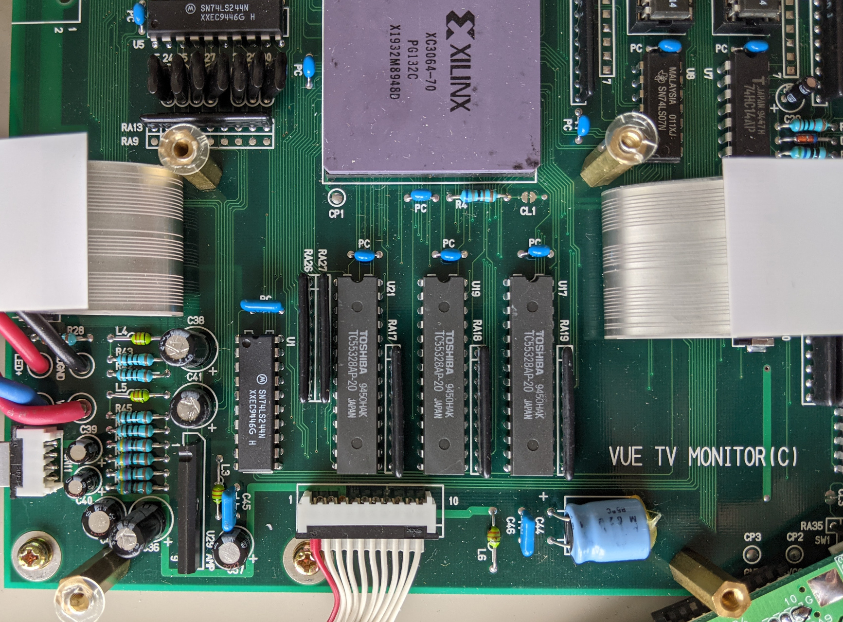
Under the MAI-VUE-X8 board there are a few stray ICs and the ribbon cables that carry video to the monitor board (left and right). The board name was hiding under here: "VUE TV MONITOR(C)", which matches "Ver. C" on the label.
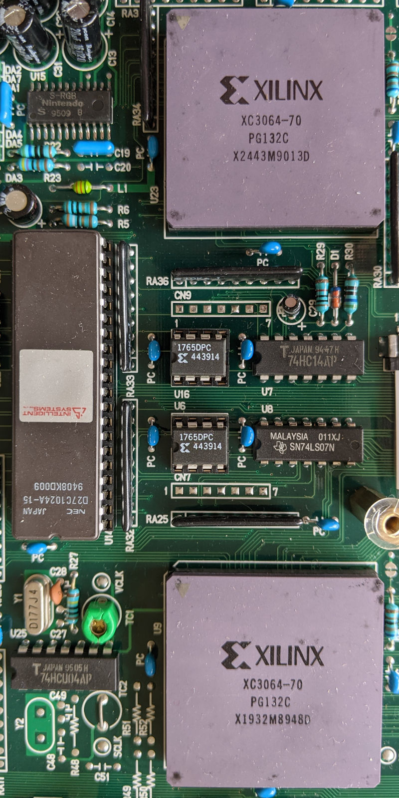
The workhorses are these two big Xilinx XC3064-70 FPGAs, which get their configuration from the 1765DPC PROMs between them. Perhaps one stores input while the other scans output.
The big NEC chip on the left (D27C1024A-15) is a 1Mbit EPROM, with an Intelligent Systems metal sticker to prevent UV erasure. I guess that at least one of the FPGAs is configured as a DSP, running a program from the EPROM.
There are eight 32KB SRAMs across the board, numbered in two groups: U12 & U13 (64KB), and U17-U22 (192KB). The 64KB might be DSP work RAM. 192KB would exactly fit two 384x256 frames with 8 bits per pixel (384x256 is the size of the Virtual Boy framebuffer, though only the top 224 rows are used). Virtual Boy graphics are only 2 bits per pixel, but each of the three non-black brightness levels can be configured by an independent 8 bit register, so 8 bits per pixel is plausible. This could be a double buffer (one taking input while the other scans output), or it could be one buffer per eye, or a double buffer for each eye at only 4 bits per pixel.
The oscillator Y1 (left, below the EPROM) seems to be associated with a VCLK test point, probably Video Clock; it's labeled D177J4, which suggests the 17.734475 MHz PAL color subcarrier. There's an unpopulated space for a second oscillator, Y2, and support components; it's grouped with the SCLK test point, maybe the Servo Clock. This may have be used when the board was configured to plug into the VUE-DEBUGGER.
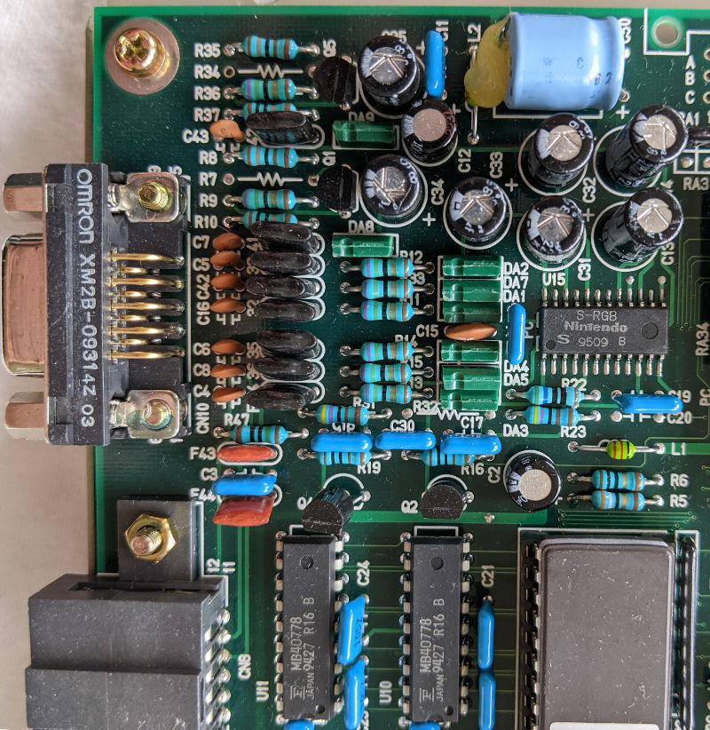
Output is produced here by two MB40778 8-bit DACs (bottom center), an S-RGB video encoder (center right), and numerous discrete components. On the left are the output connectors: CN10 at top is RGB, CN8 at bottom is AV multi-out. I guess that each DAC handles one channel, connected to the red and green inputs of the S-RGB.

There are three jumpers on the bottom, and one that goes to (and through) the Virtual Boy board, strategically glued. Version C might have still needed a few fixes, or maybe these are used to retrofit a particular MAI-VUE board, or they could be specific to the standalone Video Boy configuration.
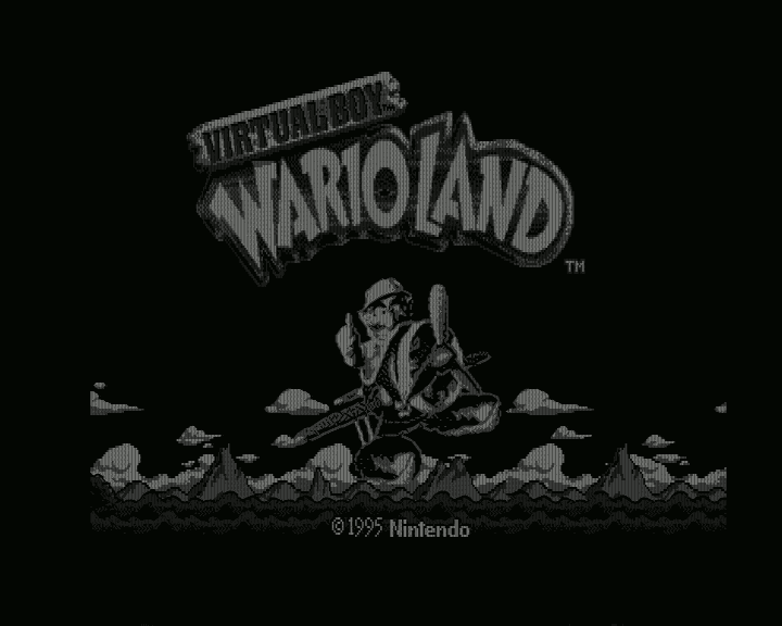
These images of Virtual Boy Wario Land come through an Elgato dongle, deinterlaced with ffmpeg filter yadif=send_field.
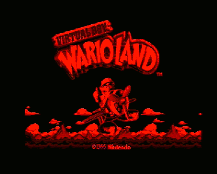
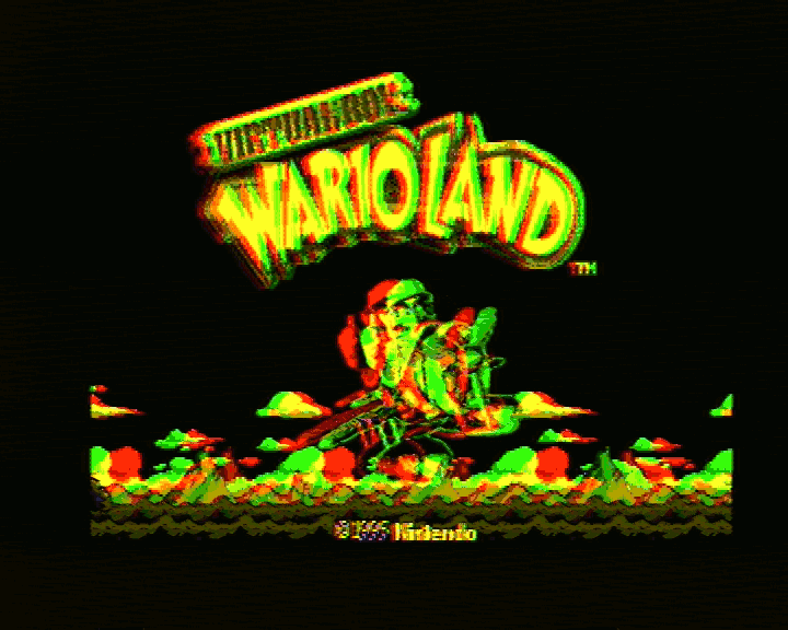
The composite video output is a bit blurry. DIP switches 7 and 8 control how the two Virtual Boy displays are combined: 8 enables the left display in red, 7 the right in green, and they can be combined (center).
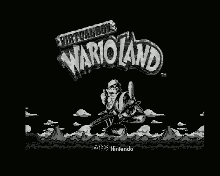
Here's the stereo effect in action, note how the colors separate on the backswing.
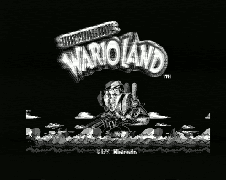
S-Video has nice crisp pixels, thanks to a higher luma resolution than composite. The Elgato isn't picking up chroma for some reason; this may be a flaw in the multi-out to S-Video cable I'm using, or the VUE Monitor may not output a color PAL S-Video signal. I use the brighter "green" output on the right when I occasionally stream Virtual Boy games.
Intelligent Systems had a VUE-DEBUGGERシリーズのご案内 site, with a section on the ビデオボーイ (Video Boy) VUE and a connection diagram.
Here's the text of the Video Boy page, based on Google Translate:
Simply connect a TV monitor that has PAL video input or RGB input to the Video Boy VUE, and a simulated stereoscopic Virtual Boy image will be displayed. By playing the Virtual Boy game cartridge on the Video Boy VUE, you can display the left-eye image and the right-eye image on the TV monitor in red and green, respectively. It is also possible to select and display an image for the left eye only or an image for the right eye only.
Since the same screen can be checked by multiple people, it is very useful during demonstrations, specification meetings, debugging, etc.
I think the PAL仕様モニタ出力ボードVUE (PAL monitor output board) was the same VUE TV Monitor board that's used in the Video Boy, configured as an expansion board for the VUE-DEBUGGER development unit. The notes on that page are similar to the Video Boy, with these two added points:
You can record your debugging work on video. This makes it easier to reproduce and check bugs that occur only occasionally, and improves debugging efficiency.
The need for programmers to look into the scanner during development is drastically reduced, reducing the strain on the eyes of the developer and improving work efficiency.
lettuce, a developer who had worked with the Video Boy, has a page with an image of the instructions, along with a longer post about working with the Virtual Boy.
Initially published 2021-05-14.